ORTZ System

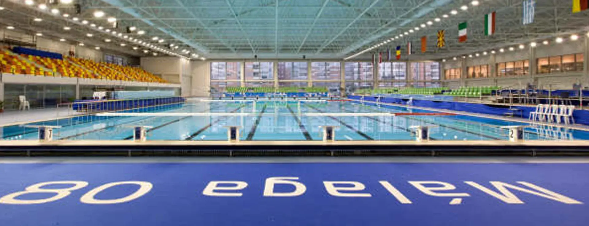
Mediterranean Games Headquarters Pool
Our ORTZ Structural System for the construction of space structures consists essentially of two types of components: nodes and bars.
The node is a spherical piece equipped with a series of threaded holes aligned with the directions of the bars that converge at the node. The availability of possible bar directions is almost unlimited, constrained only by the minimum angle two adjacent bars must maintain to avoid interference.
The bars are tubular and have conical sleeves welded to their ends. These sleeves feature axial holes traversed by specially designed bolts with two threaded sections in opposite directions, separated by a truncated cone surface. This surface, once assembled, rests on the external part of the spheres. The dual-threaded design allows a single tightening motion to secure both the sphere to the bolt and the bolt to the bar through nuts housed in the bolt's larger diameter section. These nuts serve to operate the bolt using a locking mechanism, ensuring the joint remains tight and resistant to vibrations.
This system enables the bolt to retract into the bar, allowing for assembly and disassembly without altering the relative positions of the two spheres it connects, even when they are in their final positions. This provides exceptional flexibility during mesh assembly and facilitates the replacement of damaged bars.
A primary design objective was achieving a system with high axial rigidity to minimize the inherent behavioral discontinuities introduced by bolted joints. This has been achieved through the bolt’s special design and the use of a solid, one-piece sphere.
Another key goal was creating a structure with similar behavior under tension and compression, maintaining proportionality between loads and deformations within the working load range. This allows for structural calculations within the elastic-linear field, ensuring high reliability.
Manufacturing Process
The manufacturing process for spatial meshes using the ORTZ system includes the following key steps:
- Bar Fabrication
- Machining of conical sleeves.
- Assembly of bar ends.
- Tube cutting.
- Welding of tubes to the conical sleeves.
- Painting the bars with oven polymerization (subcontracted).
- Marking and classification for shipment. - Sphere Fabrication
- Machining: drilling and threading holes.
- Surface preparation and painting.
- Classification and preparation for shipment.
A unique feature of the bar manufacturing process is the welding, performed after the ends are positioned on the welding machine’s bench. The spacing between end screws is defined by this positioning, avoiding dimensional errors from intermediate elements such as screws, sleeves, and tubes. This method allows very tight tolerances in bar production, limited only by welding process variation.
The welding process occurs in an automatic installation under a protective gas atmosphere. This setup uses CNC-controlled positioning to determine the bar’s exact length based on computer-generated specifications.
This manufacturing system achieves a dimensional tolerance of 0.3 mm for bar lengths.
The machining of threaded holes in spheres is performed on a custom CNC machine integrated with CAD-CAM systems. This machine operates automatically, performing drilling, countersinking, and threading while repositioning the sphere for each hole. Operators only load raw materials and input CNC programs.
Surface Protection
Bar protection varies according to the client’s specifications, with epoxy or polyester resin coatings being the most common. These coatings are applied electrostatically and polymerized in an oven, achieving a solid layer of no less than 60 microns. Surface preparation involves degreasing and phosphate cleaning or mechanical brushing and blasting if rust is present or to improve paint adhesion.
For higher protection, bars may undergo electro-galvanizing or other treatments for environments prone to corrosion, ensuring airtight sealing without compromising flexibility.
Spheres typically undergo similar treatments, though larger spheres may require alternative methods due to their thickness. This can include blasting, primer application, and finishing coats of chlorinated rubber or epoxy paint.
Surface treatments are not intrinsic to the ORTZ system and must be agreed upon with the client.
Quality Control
Quality control for ORTZ system components includes:
- Material Reception Controls.
- Internal Manufacturing Controls.
Those in the first group can be subdivided into:
- Dimensional and visual controls, which are carried out in our workshops, as well as some metallurgical tests, such as hardness testing, etc.
- More complex metallurgical controls (e.g., metallographic analyses, radiographs, etc.), which are subcontracted to specialized laboratories; primarily to the laboratories of the INASMET and CEIT centers.
The specific aspects related to the characteristics controlled in each component, subassembly, or finished piece of the system are described in greater detail in the Quality Control Standards and in the control guidelines specifically developed for this manufacturing process.


